


SMFT-1000 Solar Tools Kit: Fluke Multifunction PV Tester and Performance Analyzer, I-V Curve Tracer
Key features
- All-in-one PV system test solution meeting IEC 62446-1 standards for Category 1 and Category 2 tests
- Open-circuit voltage (VOC) measurement at the PV module/string up to 1000 V DC
- Short-circuit (ISC) current measurement at the PV module/string up to 20 A DC
- On-location I-V curve results compares manufacturer I-V curve data to measured data on the analyzer screen
- Compatible with Fluke TruTest™ data management software
Product overview: SMFT-1000 Solar Tools Kit: Fluke Multifunction PV Tester and Performance Analyzer, I-V Curve Tracer

All-in-one test solution to verify PV system performance and safety, expedite client reporting.
Test that PV systems are performing to their optimal power output as well as operating safely with the Fluke SMFT-1000 multifunction tester with I-V curve tracing. Designed for PV professionals that provide installation, commissioning and maintenance services to systems that operate at 1000 V DC or under, the SMFT-1000 provides a complete PV testing solution that conforms to IEC 62446-1 standards. Through Fluke’s TruTest™ Software, measurement data from solar site installation and commissioning testing can be easily imported, organized and analyzed for effortless reporting without having to bring a laptop on-site.
Critical testing features for periodic inspection of PV systems
Full sequence safety testing – IEC 62446-1 Category 1:
- Protective resistance earth (Rpe)
- Voltage on open circuit (Voc)
- Short circuit current (Isc)
- Insulation resistance (Rins)
- Polarity
ROI and system performance testing – IEC 62446-1 Category 2:
- I-V Curve tracing and software analysis with TruTest
- Irradiance, temperature, tilt, cardinal direction
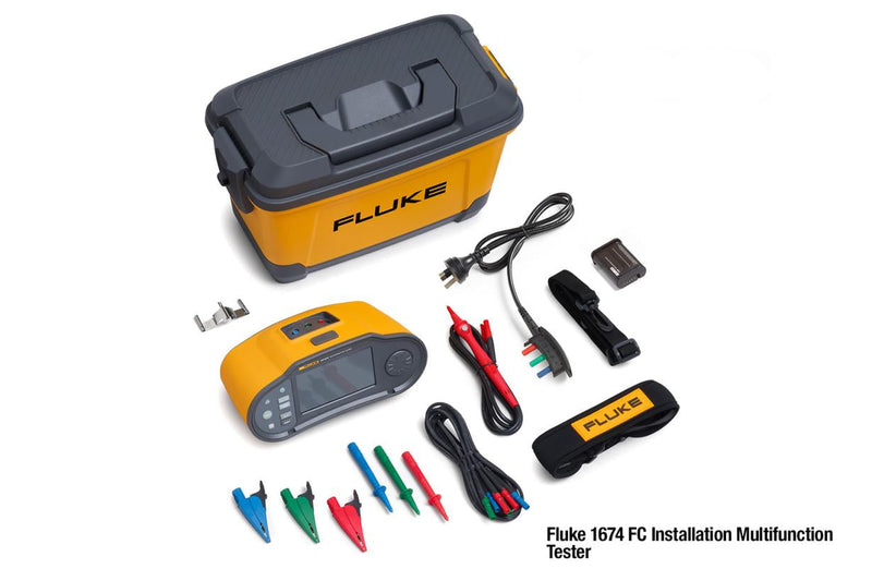
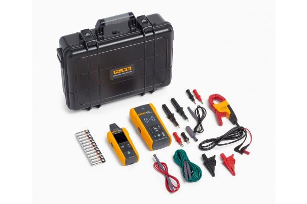
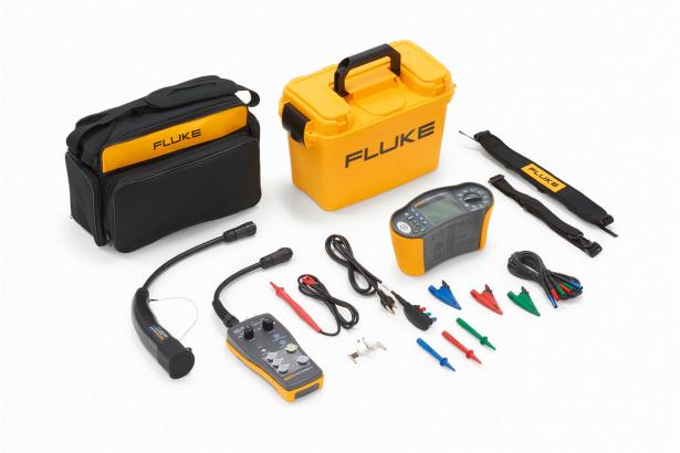
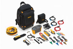
What's in the box:
- Fluke SMFT-1000-BP Professional Tool Backpack
- SMFT-1000 Multifunction PV Analyzer
- Carry Strap
- Fuse Pack
- Adapter Cable IRDA Optical-to-USB
- Zero Adapter
- IRR2-BT Wireless Solar Irradiance Meter Pro
- 80PR-IRR External Temperature Probe
- Mounting Bracket for solar panel
- Carry Case
- i100 AC/DC Current Clamp 100 A
- TPAK Magnet Set
- TP1000 Test Probe with Remote Test Button
- TL1000 Test Lead Set
- TL1000-MC4 Test Lead Set
- TL1000/30M Test Lead on Reel
- Coupler set
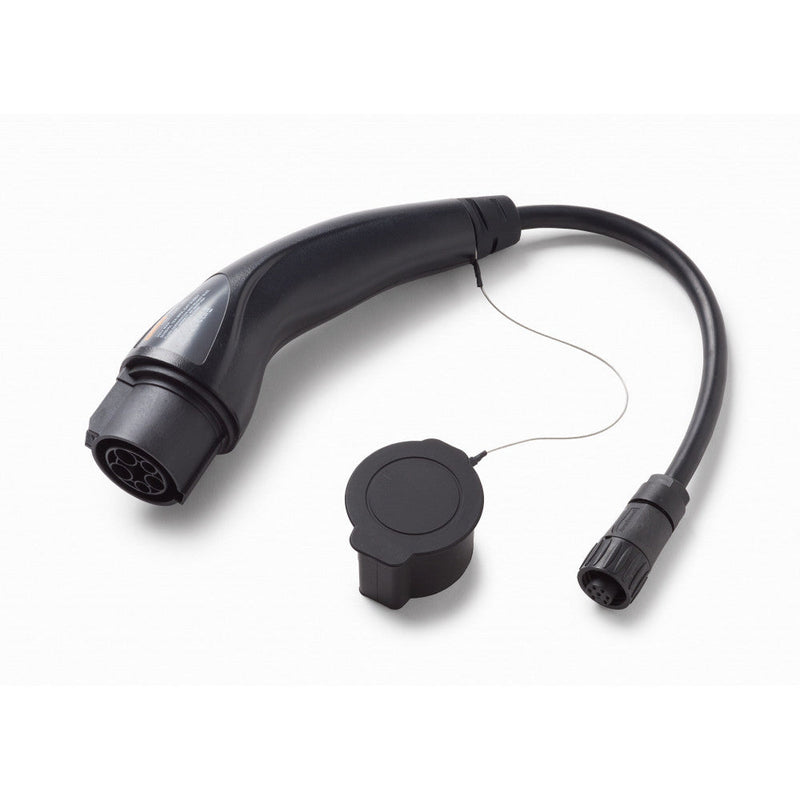
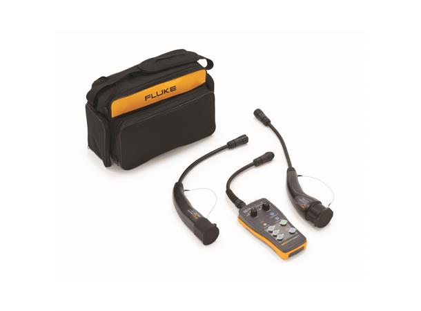
Wireless Irradiance Meter: No leads required
To perform precise I-V curve measurements, real time irradiance and temperature data is needed. The included IRR2-BT irradiance meter wirelessly connects to the SMFT-1000 to communicate data in real time, providing the most accurate I-V curve measurements possible. If the wireless connection is interrupted for any reason, the IRR2-BT will continue recording data for up to 17 hours that can later be matched to tests taken with the SMFT-1000.
It’s a hassle to change the configuration of test leads constantly while doing different tests. With Fluke’s “Keep the Leads” system, less time is wasted on set-up, and less user errors occur while testing PV systems. Now you can get more testing done in the field in less time


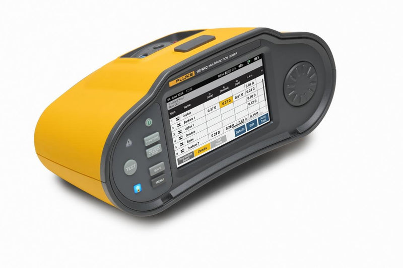
Color Screen with Integrated Interface: On-screen instructions provide an easy walkthrough of tests
Switch the SMFT-1000 to Auto Test Mode to perform an automatic sequence of tests in a variety of combinations:
- With insulation test or without insulation test
- IEC 62446-1 testing for Category 1 or Category 1 and 2
- IEC 62446-1 testing for Protection Class I or Protection Class II
On-location I-V curve results: compare manufacturer I-V curve data to measured data instantly
While taking an I-V curve reading in the field, the SMFT-1000 will display the curve as it loads in the test data, against the module specifications as defined by the manufacturer. This makes it easy to immediately confirm measurements without the use of a laptop or tablet. Run the I-V curve test on new installations to confirm they are working according to the site specifications, or to test if existing modules or strings are working to their expected performance levels.


Record visual inspections, then manage data with TruTest™ Solar Software
To meet PV system IEC regulations for visual inspections, the SMFT-1000 features a convenient setting in which to record observations directly to the memory. Later, the information can be downloaded to the TruTest™ software and incorporated into the project report.
TruTest™ allows for solar asset management, data storage and reporting on a single platform. Whether you are analyzing panel efficiency through I-V curves, or safety testing the system through the Category 1 test regime in conformance to IEC 62446-1, proper data management is critical for producing easy-to-understand reports for clients. TruTest™ Software allows you to quickly and easily import measurement results directly from your solar multifunction tester to computer, organize and analyze the data, compare individual asset data against previous measurements imported and provide a comprehensive and visual client report.
- Easily manage measurement data from solar site installation and commissioning testing
- Quickly create inspections and reports compliant with IEC 62446-1 and other directives
- I-V curve analysis with easy pass/fail visuals; see changes in I-V curve over multiple site visits
- Compare site data to previous site data to see changes over time
- Download your free 60-day demo version of TruTest™. Purchase a software key to unlock the Lite or Advanced version.
Specification
| Fluke SMFT-1000 Multifunction PV Analyzer | |||
| Protective conductor resistance (RLo) | |||
| Display range | Measuring range | Resolution | Accuracy |
| 0.00 Ω - 19.99 Ω | 0.20 Ω - 19.99 Ω | 0.01 Ω | ± (2 % + 2 Digit) |
| 20.0 Ω- 199.9 Ω | 20.0 Ω - 199.9 Ω | 0.1 Ω | ± (2 % + 2 Digit) |
| 200 Ω - 2000 Ω | 200 Ω - 2000 Ω | 1 Ω | ± (5 % + 2 Digit) |
| Test current | ≥ 200 mA (≤ 2Ω + Rcomp) | ||
| Test voltage | 4 V DC … 10 V DC | ||
| Polarity reversing | Yes | ||
| Test lead zero (Rcomp) | Up to 3 Ω | ||
| PV module/PV string, open-circuit voltage (Voc) | |||
| Display range | Measuring range | Resolution | Accuracy |
| 0.0 V - 99.9 V | 5.0 V - 99.9 V | 0.1 V | ± (0.5 % + 2 Digit) |
| 100 V - 1000 V | 100 V - 1000 V | 1 V | ± (0.5 % + 2 Digit) |
| Polarity test | Yes | ||
| PV module/PV string, short-circuit current (Is/c) | |||
| Display range | Measuring range | Resolution | Accuracy |
| 0.0 A - 20.0 A | 0.2 A - 20.0 A | 0.1 A | ± (1 % + 2 Digit) |
| Insulation resistance (RINS) | |||
| Display range | Measuring range | Resolution | Accuracy |
| 0.00 MΩ - 99.99 MΩ | 0.20 MΩ - 99.99 MΩ | 0.01 MΩ | ± (5 % + 5 Digit) |
| 100.0 MΩ - 199.9 MΩ | 100.0 MΩ - 199.9 MΩ | 0.1 MΩ | ± (10 % + 5 Digit) |
| 200 MΩ - 999 MΩ | 200 MΩ - 999 MΩ | 1 MΩ | ± (20 % + 5 Digit) |
| Measuring range | Resolution | Accuracy | |
| Test voltage @ no load | 50 V / 100 V / 250 V up to 199.9 MΩ 500 V / 1000 V up to 999 MΩ |
1 V | 0 % to + 20 % |
| Test voltage @ ≥ 1 mA | 250 V @ 250 kΩ 500 V @ 500 kΩ 1000 V @ 1 MΩ |
1 V | 0 % to + 10 % |
| Testing current | Min. 1 mA (@ 250 kΩ / 500 kΩ / 1 MΩ) Max. 1.5 mA (short circuit) |
||
| Blocking diode checking (Vbd) | |||
| Display range | Measuring range | Resolution | Accuracy |
| 0.00 V DC - 6.00 V DC | 0.50 V DC - 6.00 V DC | 0.01 V DC | ± (5 % + 10 Digit) |
| Surge protection device (SPD) | |||
| Display range | Measuring range | Resolution | Accuracy |
| 0 V DC - 1000 V DC | 50 V DC - 1000 V DC | 1 V DC | ± (10 % + 5 Digit) |
| AC/DC voltage measurement via 4 mm test sockets | |||
| Display range | Measuring range | Resolution | Accuracy |
| 0.0 V AC - 99.9 V AC | 5.0 V AC - 99.9 V AC | 0.1 V | ± (2.5 % + 2 Digit) |
| 100 V AC - 700 V AC | 100 V AC - 700 V AC | 1 V | ± (2.5 % + 2 Digit) |
| 0.0 V DC - 99.9 V DC | 5.0 V DC - 99.9 V DC | 0.1 V | ± (2.5 % + 2 Digit) |
| 100 V DC - 1000 V DC | 100 V DC - 1000 V DC | 1 V | ± (2.5 % + 2 Digit) |
| Detection AC/DC | Yes (Automatic) | ||
| + / - polarity check | Yes | ||
| AC/DC current with i100 clamp | |||
| Display range | Measuring range | Resolution | Accuracy (DC, AC 50 Hz/60 Hz) |
| 0.0 A DC – 100 A DC | 1.0 A DC – 100 A DC | 0.1 A | ± (5 % + 2 Digit) * |
| 0.0 A AC – 100 A AC TRMS | 1.0 A AC – 100 A AC TRMS | 0.1 A | ± (5 % + 2 Digit) * |
| * i100 clamp tolerances not inclusive | |||
| i100 Clamp Tolerances | |||
| Display range | Measuring range | Output signal | Accuracy (DC, AC 50 Hz/60 Hz) |
| N/A | 1 A - 100 A DC or AC < 1 kHz | 10 mV/A AC/DC | ± (1.5 % + 0.1 A) |
| AC/DC Power measurement (with i100 clamp) | |||
| Display range | Measuring range | Resolution | Accuracy (DC, AC 50 Hz/60 Hz) |
| 0.0 V AC - 700 V AC 0.0 V DC - 1000 V DC |
5.0 V AC - 700 V AC 5.0 V DC - 1000 V DC |
0.1 V | ± (2.5 % + 2 Digit) |
| 0 A AC/DC - 100 A AC/DC | 1 A AC/DC- 100 A AC/DC | 0.1 A | ± (6.5 % + 3 Digit) |
| 0 kW/kVA – 100 kW/kVA | 5 kW/kVA – 100 kW/kVA | 1 kW/kVA | ± (10 % + 4 Digit) |
| General Specifications | |||
| SMFT-1000 size | 10 cm x 25.0 cm x 12.5 cm (3.8 in x 9.8 in x 4.9 in) | ||
| SMFT-1000 weight | 1.4 kg (3.09 lb) | ||
| Battery | 6 AA IEC LR6 | ||
| Operating temperature | 0 °C to 50 °C (32 °F to 122 °F) | ||
| Storage temperature | -30 °C to 60 °C (-22 °F to 140 °F) batteries removed | ||
| Operating altitude | up to 2000 m | ||
| Storage altitude | up to 2000 m | ||
| Safety | |||
| SMFT-1000 PV Analyzer | IEC 61010-1 Pollution Degree 2 IEC 61010-2-034 CAT III 1000 V dc, CAT III 700 V AC |
||
| i100 Current Clamp | IEC 61010-2-032, Type D (for insulated conductors), 1000 V | ||
| Accessories | IEC 61010-031 | ||
| TL1000-MC4 | CAT III 1500 V, 20 A | ||
| TP1000 Remote Probe (with cap) | CAT IV 600 V, CAT III 1000 V, 10 A | ||
| TP1000 Remote Probe (without cap) | CAT II 1000 V, 10 A | ||
| TL1000 Test Leads | CAT III 1000 V, 10 A | ||
| TL1000/30M Test Leads | CAT III 1000 V, CAT IV 600 V, 5 A (on reel) 10 A (fully extended) |
||
| TP74 Test Probes (with cap) | CAT III 1000 V, 10 A | ||
| TP74 Test Probes (without cap) | CAT II 1000 V, 10 A | ||
| AC285 Alligator Clip | CAT III 1000 V, 10 A | ||
| Performance | IEC 61557-1, IEC 61557-2, IEC 61557-4, IEC 61557-10 | ||
| Electromagnetic Compatibility (EMC) | |||
| International | IEC 61326-1: Portable Electromagnetic Environment, CISPR 11: Group 1, Class A Group 1: Equipment has intentionally generated and/or uses conductively-coupled radio frequency energy that is necessary for the internal function of the equipment itself. Class A: Equipment is suitable for use in all establishments other than domestic and those directly connected to a low-voltage power supply network that supplies buildings used for domestic purposes. There may be potential difficulties in ensuring electromagnetic compatibility in other environments due to conducted and radiated disturbances. Caution: This equipment is not intended for use in residential environments and may not provide adequate protection to radio reception in such environments. |
||
| Wireless Radio Module | |||
| Frequency Range | 2.402 GHz to 2.480 GHz | ||
| Output Power | 8 dBm | ||
Includes:
- Fluke SMFT-1000-BP Professional Tool Backpack
- SMFT-1000 Multifunction PV Analyzer
- Carry Strap
- Fuse Pack
- Adapter Cable IRDA Optical-to-USB
- Zero Adapter
- IRR2-BT Wireless Solar Irradiance Meter Pro
- 80PR-IRR External Temperature Probe
- Mounting Bracket for solar panel
- Carry Case
- i100 AC/DC Current Clamp 100 A
- TPAK Magnet Set
- TP1000 Test Probe with Remote Test Button
- TL1000 Test Lead Set
- TL1000-MC4 Test Lead Set
- TL1000/30M Test Lead on Reel
- Coupler set
| Shipping | This Item Ships from Fremantle, Perth, Western Australia |
Please allow 2 - 10 days for your order to arrive.
Although Most Stocked Products will generally Ship Overnight. We source products from all over the world to bring you epic offers and the lowest prices. This means sometimes you have to wait a little longer to get your order but it's always worth it!
Returns are easy.
simply contact us for a returns number and send your item to our returns centre for fast processing. We'll get you a replacement or refund in a snap!
Description
SMFT-1000 Solar Tools Kit: Fluke Multifunction PV Tester and Performance Analyzer, I-V Curve Tracer
Key features
- All-in-one PV system test solution meeting IEC 62446-1 standards for Category 1 and Category 2 tests
- Open-circuit voltage (VOC) measurement at the PV module/string up to 1000 V DC
- Short-circuit (ISC) current measurement at the PV module/string up to 20 A DC
- On-location I-V curve results compares manufacturer I-V curve data to measured data on the analyzer screen
- Compatible with Fluke TruTest™ data management software
Product overview: SMFT-1000 Solar Tools Kit: Fluke Multifunction PV Tester and Performance Analyzer, I-V Curve Tracer
All-in-one test solution to verify PV system performance and safety, expedite client reporting.
Test that PV systems are performing to their optimal power output as well as operating safely with the Fluke SMFT-1000 multifunction tester with I-V curve tracing. Designed for PV professionals that provide installation, commissioning and maintenance services to systems that operate at 1000 V DC or under, the SMFT-1000 provides a complete PV testing solution that conforms to IEC 62446-1 standards. Through Fluke’s TruTest™ Software, measurement data from solar site installation and commissioning testing can be easily imported, organized and analyzed for effortless reporting without having to bring a laptop on-site.
Critical testing features for periodic inspection of PV systems
Full sequence safety testing – IEC 62446-1 Category 1:
- Protective resistance earth (Rpe)
- Voltage on open circuit (Voc)
- Short circuit current (Isc)
- Insulation resistance (Rins)
- Polarity
ROI and system performance testing – IEC 62446-1 Category 2:
- I-V Curve tracing and software analysis with TruTest
- Irradiance, temperature, tilt, cardinal direction
What's in the box:
- Fluke SMFT-1000-BP Professional Tool Backpack
- SMFT-1000 Multifunction PV Analyzer
- Carry Strap
- Fuse Pack
- Adapter Cable IRDA Optical-to-USB
- Zero Adapter
- IRR2-BT Wireless Solar Irradiance Meter Pro
- 80PR-IRR External Temperature Probe
- Mounting Bracket for solar panel
- Carry Case
- i100 AC/DC Current Clamp 100 A
- TPAK Magnet Set
- TP1000 Test Probe with Remote Test Button
- TL1000 Test Lead Set
- TL1000-MC4 Test Lead Set
- TL1000/30M Test Lead on Reel
- Coupler set
Wireless Irradiance Meter: No leads required
To perform precise I-V curve measurements, real time irradiance and temperature data is needed. The included IRR2-BT irradiance meter wirelessly connects to the SMFT-1000 to communicate data in real time, providing the most accurate I-V curve measurements possible. If the wireless connection is interrupted for any reason, the IRR2-BT will continue recording data for up to 17 hours that can later be matched to tests taken with the SMFT-1000.
It’s a hassle to change the configuration of test leads constantly while doing different tests. With Fluke’s “Keep the Leads” system, less time is wasted on set-up, and less user errors occur while testing PV systems. Now you can get more testing done in the field in less time
Color Screen with Integrated Interface: On-screen instructions provide an easy walkthrough of tests
Switch the SMFT-1000 to Auto Test Mode to perform an automatic sequence of tests in a variety of combinations:
- With insulation test or without insulation test
- IEC 62446-1 testing for Category 1 or Category 1 and 2
- IEC 62446-1 testing for Protection Class I or Protection Class II
On-location I-V curve results: compare manufacturer I-V curve data to measured data instantly
While taking an I-V curve reading in the field, the SMFT-1000 will display the curve as it loads in the test data, against the module specifications as defined by the manufacturer. This makes it easy to immediately confirm measurements without the use of a laptop or tablet. Run the I-V curve test on new installations to confirm they are working according to the site specifications, or to test if existing modules or strings are working to their expected performance levels.
Record visual inspections, then manage data with TruTest™ Solar Software
To meet PV system IEC regulations for visual inspections, the SMFT-1000 features a convenient setting in which to record observations directly to the memory. Later, the information can be downloaded to the TruTest™ software and incorporated into the project report.
TruTest™ allows for solar asset management, data storage and reporting on a single platform. Whether you are analyzing panel efficiency through I-V curves, or safety testing the system through the Category 1 test regime in conformance to IEC 62446-1, proper data management is critical for producing easy-to-understand reports for clients. TruTest™ Software allows you to quickly and easily import measurement results directly from your solar multifunction tester to computer, organize and analyze the data, compare individual asset data against previous measurements imported and provide a comprehensive and visual client report.
- Easily manage measurement data from solar site installation and commissioning testing
- Quickly create inspections and reports compliant with IEC 62446-1 and other directives
- I-V curve analysis with easy pass/fail visuals; see changes in I-V curve over multiple site visits
- Compare site data to previous site data to see changes over time
- Download your free 60-day demo version of TruTest™. Purchase a software key to unlock the Lite or Advanced version.
Specification
| Fluke SMFT-1000 Multifunction PV Analyzer | |||
| Protective conductor resistance (RLo) | |||
| Display range | Measuring range | Resolution | Accuracy |
| 0.00 Ω - 19.99 Ω | 0.20 Ω - 19.99 Ω | 0.01 Ω | ± (2 % + 2 Digit) |
| 20.0 Ω- 199.9 Ω | 20.0 Ω - 199.9 Ω | 0.1 Ω | ± (2 % + 2 Digit) |
| 200 Ω - 2000 Ω | 200 Ω - 2000 Ω | 1 Ω | ± (5 % + 2 Digit) |
| Test current | ≥ 200 mA (≤ 2Ω + Rcomp) | ||
| Test voltage | 4 V DC … 10 V DC | ||
| Polarity reversing | Yes | ||
| Test lead zero (Rcomp) | Up to 3 Ω | ||
| PV module/PV string, open-circuit voltage (Voc) | |||
| Display range | Measuring range | Resolution | Accuracy |
| 0.0 V - 99.9 V | 5.0 V - 99.9 V | 0.1 V | ± (0.5 % + 2 Digit) |
| 100 V - 1000 V | 100 V - 1000 V | 1 V | ± (0.5 % + 2 Digit) |
| Polarity test | Yes | ||
| PV module/PV string, short-circuit current (Is/c) | |||
| Display range | Measuring range | Resolution | Accuracy |
| 0.0 A - 20.0 A | 0.2 A - 20.0 A | 0.1 A | ± (1 % + 2 Digit) |
| Insulation resistance (RINS) | |||
| Display range | Measuring range | Resolution | Accuracy |
| 0.00 MΩ - 99.99 MΩ | 0.20 MΩ - 99.99 MΩ | 0.01 MΩ | ± (5 % + 5 Digit) |
| 100.0 MΩ - 199.9 MΩ | 100.0 MΩ - 199.9 MΩ | 0.1 MΩ | ± (10 % + 5 Digit) |
| 200 MΩ - 999 MΩ | 200 MΩ - 999 MΩ | 1 MΩ | ± (20 % + 5 Digit) |
| Measuring range | Resolution | Accuracy | |
| Test voltage @ no load | 50 V / 100 V / 250 V up to 199.9 MΩ 500 V / 1000 V up to 999 MΩ |
1 V | 0 % to + 20 % |
| Test voltage @ ≥ 1 mA | 250 V @ 250 kΩ 500 V @ 500 kΩ 1000 V @ 1 MΩ |
1 V | 0 % to + 10 % |
| Testing current | Min. 1 mA (@ 250 kΩ / 500 kΩ / 1 MΩ) Max. 1.5 mA (short circuit) |
||
| Blocking diode checking (Vbd) | |||
| Display range | Measuring range | Resolution | Accuracy |
| 0.00 V DC - 6.00 V DC | 0.50 V DC - 6.00 V DC | 0.01 V DC | ± (5 % + 10 Digit) |
| Surge protection device (SPD) | |||
| Display range | Measuring range | Resolution | Accuracy |
| 0 V DC - 1000 V DC | 50 V DC - 1000 V DC | 1 V DC | ± (10 % + 5 Digit) |
| AC/DC voltage measurement via 4 mm test sockets | |||
| Display range | Measuring range | Resolution | Accuracy |
| 0.0 V AC - 99.9 V AC | 5.0 V AC - 99.9 V AC | 0.1 V | ± (2.5 % + 2 Digit) |
| 100 V AC - 700 V AC | 100 V AC - 700 V AC | 1 V | ± (2.5 % + 2 Digit) |
| 0.0 V DC - 99.9 V DC | 5.0 V DC - 99.9 V DC | 0.1 V | ± (2.5 % + 2 Digit) |
| 100 V DC - 1000 V DC | 100 V DC - 1000 V DC | 1 V | ± (2.5 % + 2 Digit) |
| Detection AC/DC | Yes (Automatic) | ||
| + / - polarity check | Yes | ||
| AC/DC current with i100 clamp | |||
| Display range | Measuring range | Resolution | Accuracy (DC, AC 50 Hz/60 Hz) |
| 0.0 A DC – 100 A DC | 1.0 A DC – 100 A DC | 0.1 A | ± (5 % + 2 Digit) * |
| 0.0 A AC – 100 A AC TRMS | 1.0 A AC – 100 A AC TRMS | 0.1 A | ± (5 % + 2 Digit) * |
| * i100 clamp tolerances not inclusive | |||
| i100 Clamp Tolerances | |||
| Display range | Measuring range | Output signal | Accuracy (DC, AC 50 Hz/60 Hz) |
| N/A | 1 A - 100 A DC or AC < 1 kHz | 10 mV/A AC/DC | ± (1.5 % + 0.1 A) |
| AC/DC Power measurement (with i100 clamp) | |||
| Display range | Measuring range | Resolution | Accuracy (DC, AC 50 Hz/60 Hz) |
| 0.0 V AC - 700 V AC 0.0 V DC - 1000 V DC |
5.0 V AC - 700 V AC 5.0 V DC - 1000 V DC |
0.1 V | ± (2.5 % + 2 Digit) |
| 0 A AC/DC - 100 A AC/DC | 1 A AC/DC- 100 A AC/DC | 0.1 A | ± (6.5 % + 3 Digit) |
| 0 kW/kVA – 100 kW/kVA | 5 kW/kVA – 100 kW/kVA | 1 kW/kVA | ± (10 % + 4 Digit) |
| General Specifications | |||
| SMFT-1000 size | 10 cm x 25.0 cm x 12.5 cm (3.8 in x 9.8 in x 4.9 in) | ||
| SMFT-1000 weight | 1.4 kg (3.09 lb) | ||
| Battery | 6 AA IEC LR6 | ||
| Operating temperature | 0 °C to 50 °C (32 °F to 122 °F) | ||
| Storage temperature | -30 °C to 60 °C (-22 °F to 140 °F) batteries removed | ||
| Operating altitude | up to 2000 m | ||
| Storage altitude | up to 2000 m | ||
| Safety | |||
| SMFT-1000 PV Analyzer | IEC 61010-1 Pollution Degree 2 IEC 61010-2-034 CAT III 1000 V dc, CAT III 700 V AC |
||
| i100 Current Clamp | IEC 61010-2-032, Type D (for insulated conductors), 1000 V | ||
| Accessories | IEC 61010-031 | ||
| TL1000-MC4 | CAT III 1500 V, 20 A | ||
| TP1000 Remote Probe (with cap) | CAT IV 600 V, CAT III 1000 V, 10 A | ||
| TP1000 Remote Probe (without cap) | CAT II 1000 V, 10 A | ||
| TL1000 Test Leads | CAT III 1000 V, 10 A | ||
| TL1000/30M Test Leads | CAT III 1000 V, CAT IV 600 V, 5 A (on reel) 10 A (fully extended) |
||
| TP74 Test Probes (with cap) | CAT III 1000 V, 10 A | ||
| TP74 Test Probes (without cap) | CAT II 1000 V, 10 A | ||
| AC285 Alligator Clip | CAT III 1000 V, 10 A | ||
| Performance | IEC 61557-1, IEC 61557-2, IEC 61557-4, IEC 61557-10 | ||
| Electromagnetic Compatibility (EMC) | |||
| International | IEC 61326-1: Portable Electromagnetic Environment, CISPR 11: Group 1, Class A Group 1: Equipment has intentionally generated and/or uses conductively-coupled radio frequency energy that is necessary for the internal function of the equipment itself. Class A: Equipment is suitable for use in all establishments other than domestic and those directly connected to a low-voltage power supply network that supplies buildings used for domestic purposes. There may be potential difficulties in ensuring electromagnetic compatibility in other environments due to conducted and radiated disturbances. Caution: This equipment is not intended for use in residential environments and may not provide adequate protection to radio reception in such environments. |
||
| Wireless Radio Module | |||
| Frequency Range | 2.402 GHz to 2.480 GHz | ||
| Output Power | 8 dBm | ||
Includes:
- Fluke SMFT-1000-BP Professional Tool Backpack
- SMFT-1000 Multifunction PV Analyzer
- Carry Strap
- Fuse Pack
- Adapter Cable IRDA Optical-to-USB
- Zero Adapter
- IRR2-BT Wireless Solar Irradiance Meter Pro
- 80PR-IRR External Temperature Probe
- Mounting Bracket for solar panel
- Carry Case
- i100 AC/DC Current Clamp 100 A
- TPAK Magnet Set
- TP1000 Test Probe with Remote Test Button
- TL1000 Test Lead Set
- TL1000-MC4 Test Lead Set
- TL1000/30M Test Lead on Reel
- Coupler set
Shipping
| Shipping | This item ships to |
Delivery & Returns
Please allow 2 - 10 days for your order to arrive.
Although Most Stocked Products will generally Ship Overnight. We source products from all over the world to bring you epic offers and the lowest prices. This means sometimes you have to wait a little longer to get your order but it's always worth it!
Returns are easy.
simply contact us for a returns number and send your item to our returns centre for fast processing. We'll get you a replacement or refund in a snap!
6 Great reasons to buy from us:
-

30 Days Return
If your product is faulty or damaged under manufacture warranty, simply send it back to us and we'll cheerfully replace it or fix the problem for you. -

Returns are Easy
Simply contact us for a returns number and send your item to our returns centre for fast processing. We'll get you a replacement or refund in a snap! -

Best Price Guarantee
In the unlikely event that you find your item cheaper at another online store, just let us know and we'll beat the competitor's pricing hands-down. -

We guarantee your satisfaction
We insist that you love everything you buy from us. If you're unhappy for any reason whatsoever, just let us know and we'll bend over backwards to make things right again. -

100% Safe & Secure
Ordering from Laserman Technologies is 100% safe and secure so you can rest easy. Your personal details are never shared, sold or rented to anyone either. -

Best Laser Warranties in the Business
Laserman the Best Laser Level, Pipe Laser and Laser Measuring Warranties in the Business - Now thats unbeatable value !!.


Related Products