Gas custody transfer flow computer calibration
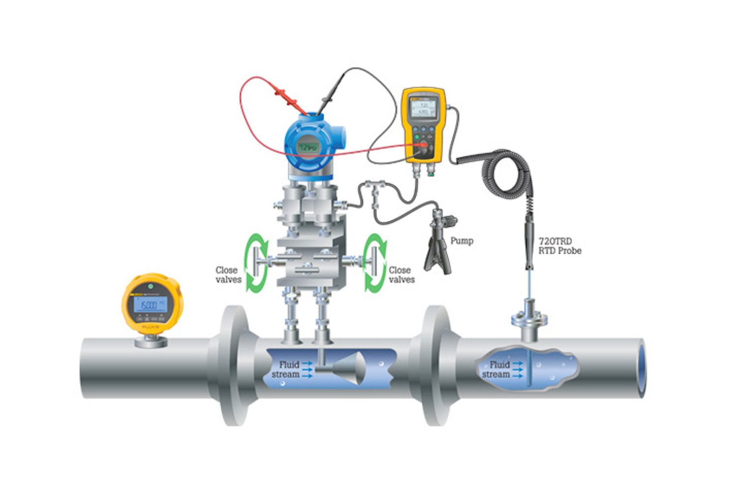
Gas custody transfer flow computers that calculate flow in pipelines by measuring the differential pressure across a flow restriction, such as an orifice plate or other differential pressure flow device, require special calibration to perform at optimum accuracy. Gas flow computers make three primary measurements to calculate flow: volumetric flow (difference in pressure across the orifice plate), static pressure in a pipeline and gas temperature. A calculation is performed using this data to determine the actual mass and volume of the gas flowing through the pipeline.

These calibrations can be made with three separate calibrators, a low pressure, high pressure and a temperature calibrator or use a multifunction calibration tool designed for this specific task.
An example of a calibrator purposed for this task is the Fluke 721 or 721Ex. It has two built in pressure ranges and the ability to measure temperature. The most popular configuration is 16 psi/1 bar on the low pressure (P1) sensor side and 1500/100 bar or 3000 psi/200 bar on the high pressure (P2) sensor side. It measures temperature using a precision RTD accessory and can display all three measurements at once if desired.
How to perform the test
To get started, isolate the flow computer from the pipeline. It is normally installed with a 5-valve manifold. If so, closing the valves on the pipeline side of the manifold should isolate it. Be sure to follow local policy and safety procedures when performing this isolation step. Set the P1 sensor of the 721 to measure inH20 and the P2 sensor to measure PSI and the temperature sensor to measure degrees Celsius or Fahrenheit as needed.
- Low pressure differential pressure calibration is performed using atmospheric pressure as a low side reference. Vent the low connection of the flow computer or pressure transmitter and connect the high-pressure connection of the flow computer or transmitter to the low-pressure port (P1) on the calibrator.
- Connect the computer (PC) to the flow computer serial or USB port. The PC will instruct the user to apply one or more test pressures to the flow computer or transmitter. For example, 0, 100 and 200 inH20. Squeeze the pump to get close to the test pressure and use the Vernier or fine pressure adjust to dial in
- Static pressure calibration will normally be applied to either the same high-pressure port of the flow computer or both the high- and low-pressure ports. Refer to the manufacturer’s instructions for details. Connect the high-pressure sensor input (P2) to the appropriate port on the flow computer or transmitter and to the high-pressure test source. The PC will instruct the pressures for the user to apply from the pressure source.
- Temperature calibration of the temperature measurement on the flow computer is done with a single temperature point at the pipeline operating temperature. Insert the RTD probe into the test thermowell and allow time for the measurement to stabilize.
- The PC will prompt the user to enter the temperature measured by the calibrator. Remove the RTD from the test thermowell and the calibration is complete.
- Flow Computers with 4 to 20 mA inputs: Many flow computers utilize a low pressure, static and temperature transmitter to convert the measured parameters into 4 to 20 mA signals. In this instance these transmitters may need individual calibration if the test results are not satisfactory (see HART Transmitter Calibration application note or video for more details). Another source for errors in this configuration is the input A/D cards of the flow computer. These can be independently tested using a mA signal source from a loop calibrator.


